Describing interactions with UML sequence diagrams
Rational Application Developer provides the capability to develop and manage sequence diagrams. A sequence diagram is an interaction diagram that can be used to describe the dynamic behavior of a system. It depicts the sequence of messages which are sent between objects in a certain interaction or scenario.
Sequence diagrams can be used at different stages during the development process:

| Within the analysis phase, a sequence diagram can be used to describe the realization of a use case that is a use case scenario. |

| Within the design phase, sequence diagrams can be more refined to show how a system accomplishes an interaction and in this case shows objects of actual design classes interacting. |
A sequence diagram consists of a group of objects their associated lifelines and the messages that these objects exchange over time during the interaction. In this context, the term object does not necessarily refer to software objects instantiated from a class. An object represents any structural thing defined by UML.
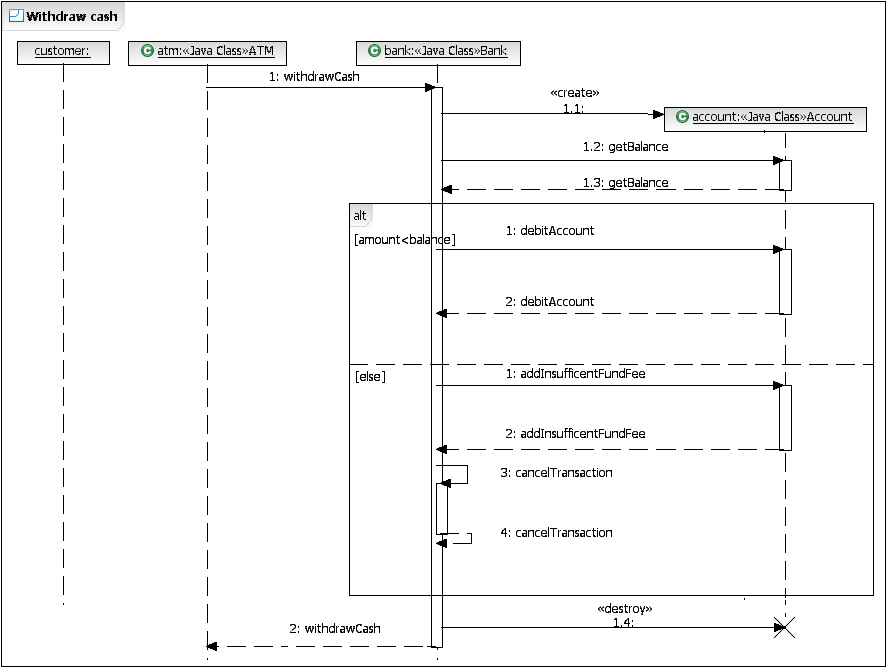
Figure | -34 provides an overview of a sample sequence diagram. It describes the scenario where a customer wants to withdraw cash from an ATM. A sequence diagram has a two-dimensional nature. The horizontal axis shows each of the objects that are involved in an interaction, while the vertical axis shows the lifelines, the messages exchanged and the sequence of creation and destruction of the objects.
Most objects that appear in a sequence diagram are in existence for the duration of the entire interaction, so their lifelines are placed at the top of the diagram. Objects can be created or destroyed during an interaction. In this case, their lifelines start or end respectively with the receipt of a corresponding message to create or destroy them.

Figure 7-34 Overview of a sequence diagram
The main focus of Rational Application Developer when using sequence diagrams is to document and visualize the dynamic behavior of a system, rather than to develop source code. The tool enables developers to create, edit, and delete the various elements of a sequence diagram such as lifelines, messages and combined fragments in a visual manner. In contrast to a class diagram, the elements of a sequence diagram are not related to existing elements, such as classes or interfaces. So changes made in a sequence diagram do not affect any code.
Rational Application Developer has two different concepts of what a sequence diagram is. The first kind of sequence diagram is created by a developer, within a project, to document development work. In this case, the developer adds lifelines, messages, and elements to the diagram to show specific object interactions. The second kind of sequence diagram is referred to as Static Method Sequence Diagram. This non-editable diagram is used to visualize the flow of messages between existing Java objects in an executing application.
|
ibm.com/redbooks |