Creating, editing, and viewing Java elements in UML class diagrams
When working with class diagrams developers can create, edit, and delete Java elements such as packages, classes, interfaces, and enum types to allow the visual development of Java application code.
To draw a class diagram, you simply select the desired elements from the palette and drag them to the class diagram editor window. This launches the appropriate wizard, such as the New Java Class wizard if you drag a Java class from the palette, that guides you in the creation of the new element. Alternatively, elements can be created directly in the Enterprise Explorer and placed on the diagram later.
Figure | -3 shows a class as it is seen when added to a class diagram. The class is rendered as specified in the UML standard.
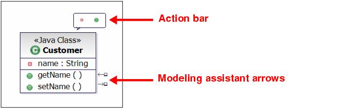
Figure 7-3 A Java class with action bar and modeling assistant arrows visible
In this case, three compartments are visible:
| The upper compartment or name compartment contains the class name and if required a stereotype. A stereotype is a string, surrounded by guillemets (angled brackets) that indicates the kind of element more precisely. In this case we have a class, but more precisely its a Java class. |
| The middle compartment is the attribute compartment and contains the attributes present in the class. |
| The lower compartment is the operation compartment and contains the operations present in the class. |
To show or hide individual compartments, right-click the class and select Filters Æ Show/Hide Compartment.
Also, when you hover the mouse cursor over a class, the action bar and the modeling assistant arrows are displayed:
| The action bar is an icon-based context menu that provides quick access to commands that allow you to edit a diagram element. In the case of a Java class, you can add fields and methods to the class. The actions, available on the action bar, are also available through Add Java in the context menu, which is presented if you right-click the class in the diagram. |
| The modeling assistant allows you to create and view relationships between the selected element and other elements such as packages, classes, or interfaces. One modeling assistant arrow points towards the element and the other points away. The arrow pointing towards the element is for incoming relationships. Thus, when creating a relationship where the selected element is the target, you would use the incoming arrow. Similarly, the arrow pointing away from the element is for outgoing relationships and is used in a similar way. |
To create a relationship from one Java element to another element, execute the following steps:
| Move the mouse cursor over the source element so that the modeling assistant is available and click the small box at the end of the outgoing arrow. |
| Drag the connector that appears and drop it on the desired element or on an empty space inside the diagram if you want to create a new element. |
| Select the required relationship type from the context menu that appears when the connector is dropped. |
You can create incoming relationships in the same way by using the incoming arrow. Alternatively, you can select the desired relationship in the tool palette and place it on the individual elements.
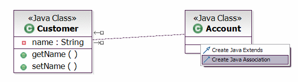
Figure 7-4 Using the Modeling Assistant to create a relationship
The modeling assistant also allows you to view related elements that are based on a specific relationship. These are elements that exist in the model but are not currently shown on the class diagram. To do this, double-click the small box at the end of the outgoing or incoming arrow and select the desired relationship from the resulting context menu as shown in Figure | -5. This is equivalent to selecting Filter Æ Show Related Elements from the element's context menu.
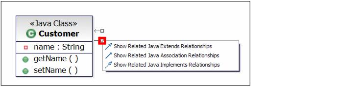
Figure 7-5 Viewing related Java elements using the modeling assistant
The context menu for a class includes several additional editing options that have not yet been discussed. Some of the additional options are as follows:
| Delete from Diagram-This option removes the visual representation of the selected element(s) from the diagram. It does not delete the element from the project. Note that when you delete Java elements from a class diagram, the underlying associations remain intact. |
| Format-This option changes the properties of the selected element that govern its appearance and location in a diagram. Modifying these properties only changes the appearance of this specific rendition of the element, it does not affect how the element is rendered elsewhere on the diagram or in another diagram. Some of the properties can be configured globally using the modeling preferences dialog. |
| Filters-This option allows you to manage the visual representation of elements in UML class diagrams but is concerned with what is visible on a diagram when the element is rendered irrespective of what the element contains. For example, UML allows a class to have operations but allows the operations to be hidden, if required, when the class is drawn on a class diagram. With the filters option you can show or hide attributes and operations, determine if operation signatures are displayed or specify if the fully qualified names of individual classes are shown. |
| Filters Æ Show Related Elements-This is a particular function of the Filters option and requires its own explanation because it is so useful. Show Related Elements helps developers to query for related elements in a diagram. As shown in Figure | -6, the Show Related Elements dialog allows you to select from a set of predefined queries. By clicking Details, you can view and change the actual relationships, along with other settings related to the selected query. |
| Refactor and Source provide the same functionality to change and edit the underlying Java code as they do when invoked on the class directly in the Enterprise Explorer. |
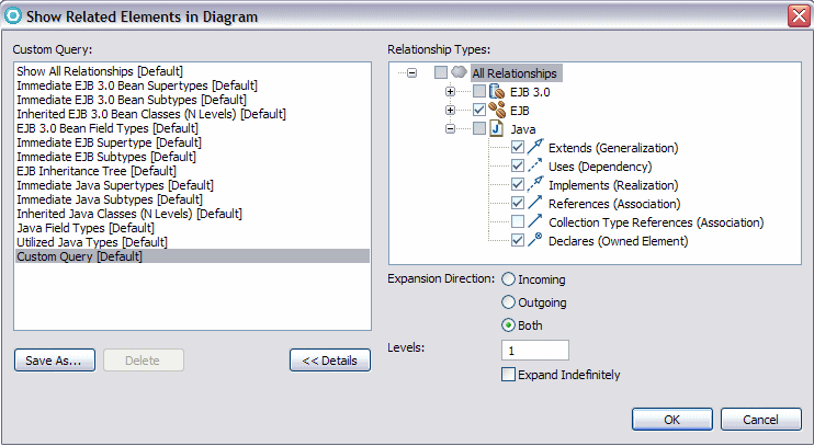
Figure 7-6 Show Related elements dialog
Figure | -7 provides an example of a class diagram showing some elements and the relationships between them.
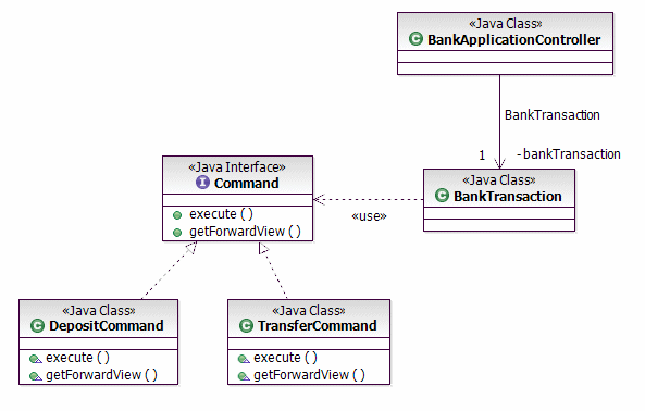
Figure 7-7 Class diagram showing different UML elements
|
ibm.com/redbooks |