UML visualization capabilities
All of these diagrams help developers to understand and document code. To provide further documentation, you can also generate Javadoc HTML documentation that contains UML diagram images. Refer to Generating Javadoc with diagrams automatically.
The UML visualization tools are applicable not only to Java classes but also to other types of artifacts, such as Web services and Enterprise JavaBeans. Rational Application Developer also supports data visualization using UML or Information Engineering notation.
Figure | -1 provides an overview of the workspace you might see when using the UML visualization capabilities:
| The center area is the UML editor. This editor is used to display and modify the different elements present in the model. |
| Built into the editor is a palette that is used to drag and drop elements onto the editor work area. The items that appear in the palette are specific to the type of project that is being visualized. The palette is only available when the diagram is editable. The palette is not displayed for topic and browse diagrams |
| The Outline view enables you to see, in miniature, the whole diagram currently being viewed with the area of the diagram you have zoomed in on highlighted. This can be very useful for finding your way around a complex diagram, because you can left click the area of the outline view that is highlighted and drag it around to see a different zoomed area. You can also change the outline view to show a tree of all the different elements that are present in the current diagram. |
| The Properties view enables you to review or change any property that is related to a selected diagram or a diagram element. |
| Finally, you can drag and drop project elements from the Enterprise Explorer or Package Explorer view directly into the editor work area to add these items to the diagram. You can, for example, drag a Java class form the Enterprise Explorer to the editor work area where it will be rendered as a UML class in the diagram. If relationships exist between the Java class you have dragged, such as an association with another class, then this will be rendered as well. |
In Figure | -1 the diagram shown was created by dragging the DepositCommand class, TransferCommand class, and Command interface to the editor work area.
In this case, the TransferCommand and DepositCommand implement the Command interface, and as you can see, UML implements relationships have also been rendered in the diagram.
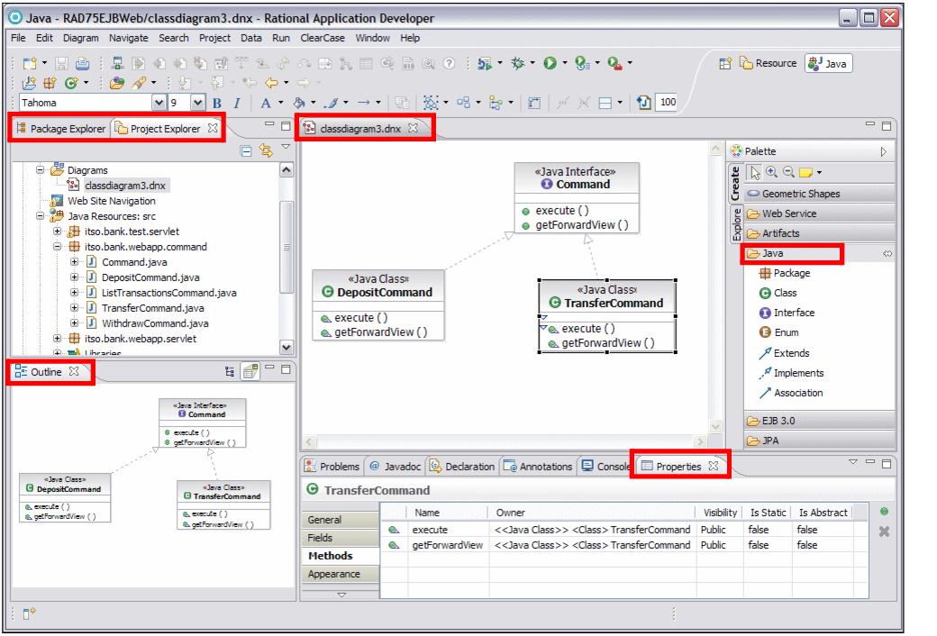
Figure 7-1 Example workspace when using the UML visualization capabilities
|
ibm.com/redbooks |