WebSphere Lombardi Edition 7.2 > Modeling processes > Basic modeling tasks
Use gateways
Gateways control the divergence and convergence of sequence lines, determining branching and merging of the paths that a run-time process can take. You can think of conditional and decision gateways as questions that are asked at a particular point in the process flow. The question has a defined set of alternative answers, which act as gates. The process cannot proceed until a valid answer is provided. You can model questions using Javascript conditions, which are evaluated before the process is allowed to proceed.
You can model the following types of gateways in your process diagram:


Be aware of the following when using gateways:
- After you drag one of the preceding icons to your process diagram, you can choose any of the available gateway types if you decide to change the behavior.
- Split and join gateways are not always paired together. You can use one without the other.
- When you model conditional and decision gateways, if all conditions evaluate to false, the process follows the default sequence line. The default sequence line is the first line that you create from the gateway to a following step, but you can change the default sequence line at any time.
To add gateways to a process diagram:
- Drag the type of gateway that you want from the palette to the process diagram. (The preceding table describes the types of gateways available.)
-
Use the Sequence Flow tool, create the necessary sequence lines to and from the gateway.
The default sequence line is the first line that you create from the gateway to a following step. You can change the default sequence line when specifying the implementation properties for a gateway. See Step 5.
- Click the gateway in the process diagram and then click the Step option in the properties.
- Type a name for the gateway.
The other fields are optional:
Name visible By default, the name that you provide for the gateway displays in the process diagram. Disable this check box if you do not want the name displayed in the diagram. Presentation Icon To use an icon other than the default provided by Lombardi, provide the pathname for the image that you want to use. Documentation Enter a description of the gateway. Gateway Type Ensure that the type of gateway you want to implement is selected from the drop-down list. The preceding table describes the types of gateways available. -
For conditional splits and joins and decision gateways, click the Implementation tab. For each outgoing sequence line, enter the condition (in JavaScript) that controls whether the path is followed. (See Example gateways to understand the types of conditions that you can define.)
Ensure that the sequence line shown as the Default Line is the one that you want the process to follow if all conditions evaluate to false. If not, use the arrow icons to move the lines until the one that you want is designated the default. (The last line in the list is the default line.)
Default sequence lines do not require a condition.
- Click Save in the main toolbar.
To continue to build a basic BPD by following the procedures in
Basic modeling tasks:
- Drag a simple split from the palette to the process diagram so that it directly precedes the Approval activity.
- In the Step option in the properties for the simple split, type the name: Split.
- Drag a simple join from the palette to the process diagram so that it immediately follows the Approval activity.
-
In the Step option in the properties for the simple join, type the name: Merge.
Add the simple split and join enables us to model the Approval and Validation steps so that the process flow continues after both of these steps are complete. If you click the Implementation option in the properties for the simple split and join, you can see that there are no conditions for these types of gateways, which means all paths are followed.
-
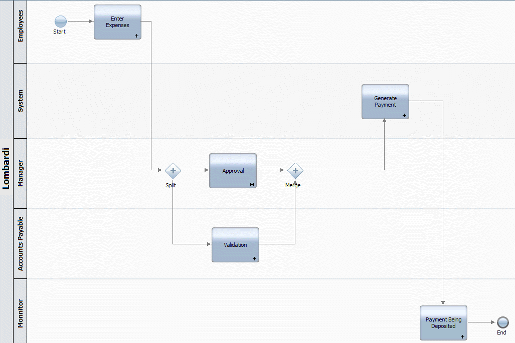
Use the Sequence Flow tool, connect the Enter Expenses activity to the simple split and then continue to connect the process components so that your diagram looks like the following image:
Parent topic: Basic modeling tasks