Network Deployment (Distributed operating systems), v8.0 > Applications > Web services > WS-Notification > WS-Notification topologies
WS-Notification in a clustered environment
WAS provides the ability to group servers together in a cluster so that the application can be protected from the failure of a single server (high availability) or so that the application workload can be spread out across a number of equivalent servers (workload balancing). The service integration bus is also configurable within the application server cluster in a variety of configurations depending upon whether you are clustering for high availability, workload management or both. For example you can choose how many messaging engines are configured in the cluster (from one up to the number of servers in the cluster) and you can choose the server (if any) to which a given messaging engine fails over if its primary server fails.
One common pattern is to configure a 1 of N core group policy for a messaging engine in which there is a single messaging engine in the cluster, and the messaging engine can move to any other server in the cluster if its host server fails. This ensures that the state associated with the messaging engine (for example event notifications and subscriptions)
is available to applications even if a specific piece of hardware fails.
Load balanced topology
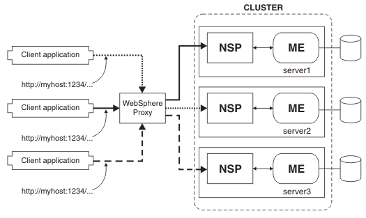
In this topology the administrator aims to share client application requests across multiple servers in the cell without overloading any particular server. This requires that all WS-Notification service points of the WS-Notification service can be considered the same - in particular that all topic namespaces are available at every WS-Notification service point of the broker.
WAS-specific WS-Addressing support in the proxy ensures that web services requests that have an affinity with a particular messaging engine (for example Resume or Destroy subscription flows) are routed back to the server in which the messaging engine is located.
The following figure shows a configuration of a clustered environment configured for load balance. Requests from three different client applications are received by a WAS proxy server, and each request is forwarded to a different single application server. Information about each request is stored by each messaging engine in a separate database. WAS-specific WS-Addressing code in the proxy, records which server received each request, and routes each subsequent request to the correct application server.
Figure 1. Example of a load balanced topology
High availability topology
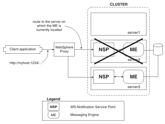
In this topology the administrator creates a cluster of servers containing a single messaging engine and WS-Notification service point, in order to ensure that should the server containing the messaging engine fail, the resources it manages (subscriptions, event notifications) remain available to the remote applications. The messaging engine is configured to fail over between the various servers in the cluster in order to provide highly available operation.
The WS-Notification service point is deployed to every server in the cluster. The resources (subscriptions, publisher registrations and pull points) are maintained in the messaging engine, so in order to execute a request the service point creates a connection to the server in which the messaging engine is currently running.
The WAS proxy server is a special type of application server that provides the initial point of entry for requests into the enterprise. For WS-Notification, a proxy server is most often used as the front-end for a cluster of application servers, where it work load balances the initial requests (such as event notifications) across the servers in the cluster. Some WS-Notification requests (such as creating a subscription) create an affinity with a specific messaging engine, and so when subsequent requests relating to that resource are received by the proxy server they are routed to the server that is currently hosting the relevant messaging engine, even if that server has changed due to a failure since the resource was created.
WAS-specific WS-Addressing support in the proxy ensures that web services requests that have an affinity with a particular messaging engine (for example Resume or Destroy subscription flows) are routed back to the server in which the messaging engine is located.
The following figure shows a configuration of a clustered environment configured for high availability. Request from client applications are received by a WAS proxy server, and forwarded to an application server within a cluster. WAS-specific WS-Addressing code in the proxy, records which server received the request. Information about the request is stored in a database by the messaging engine for the cluster. If the application server fails, then its place is taken by another server in the cluster. The WS-Addressing code in the proxy reroutes subsequent requests to the replacement application server.
Figure 2. Example of a high availability topology
Load balanced high availability topology
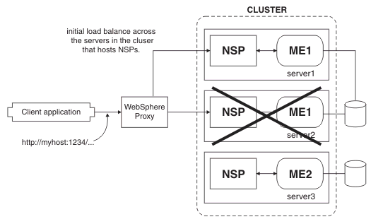
This topology is a combination of the load-balanced topology and the high-availability topology. In this topology there is more than one messaging engine in the cluster (where the number of messaging engines is less than or equal to the number of servers). Initial requests received by the proxy server are load balanced across the cluster, to those servers that host WS-Notification service points. Subsequent requests for a resource that is created by that request (that is a subscription) are routed back to the affine messaging engine, even where it might have failed across to a different server in the cluster.
Note that this would include the case where more than one of the messaging engines in the cluster is currently located on a single server as a result of a failover. In this case it remains important that the Service Point connects to the correct messaging engine.
The following figure shows a configuration of a clustered environment configured for high availability and load balance. This cluster has three application servers. Two of these servers use the same messaging engine, and the third uses a different messaging engine. A request from a client application is received by a WAS proxy server, and forwarded to one of the application servers that shares a messaging engine. WAS-specific WS-Addressing code in the proxy, records which server received the request. The application server fails, and its place is taken by one of the other two servers. The WS-Addressing code in the proxy routes subsequent requests for a resource that is created by the initial request (that is a subscription) to the surviving application server that uses the same messaging engine.
Figure 3. Example of a high availability and load balanced topology

WS-Notification
Provide highly available (HA) topologies for WS-Notification
High availability and workload sharing for service integration technologies
Use WS-Notification for publish and subscribe messaging for web services
Secure WS-Notification
Related
WS-Notification roles and goals
WS-Notification troubleshooting tips
 Concept topic

